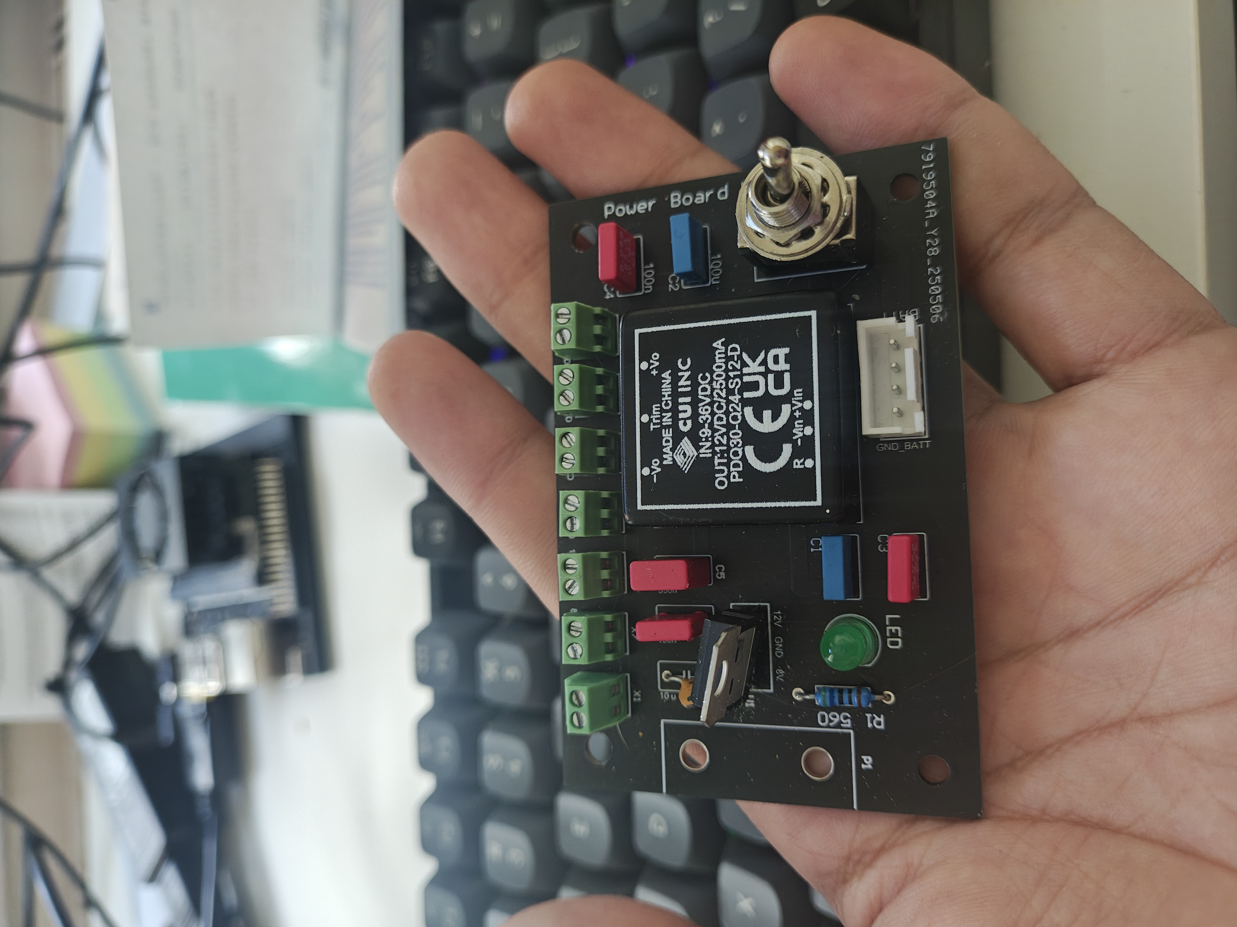
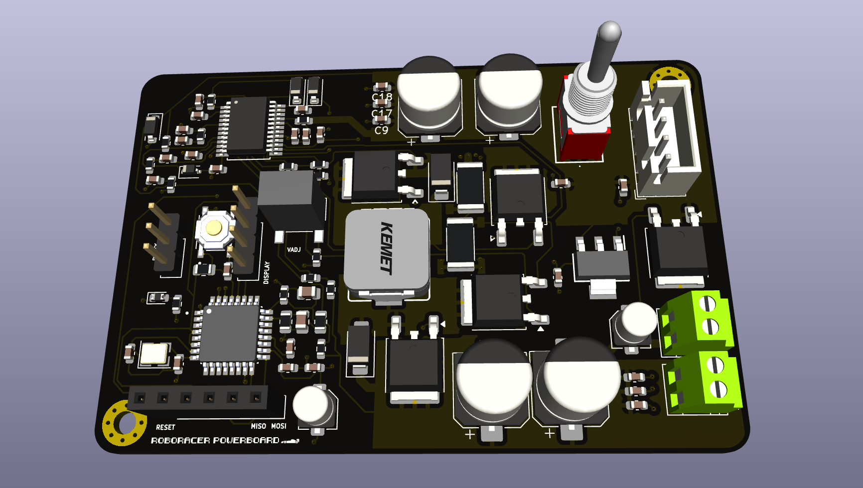
So here’s what we did with our custom PCB for the F1TENTH car. I’m going to walk you through what we changed and why, because the original setup although good and does the task I felt there are some room for improvments
The Problem with the Original Setup
The original F1TENTH PCB worked fine for basic functionality, but we ran into several issues during development and testing that made us think we could do better.

Here’s what we noticed: you’re working on your car, everything seems fine, and then suddenly your Jetson starts getting laggy. Or the whole thing just stops working mid-run. The problem? No easy way to know what’s going wrong. Is it the battery? Is something overheating? You basically had to guess.
The wiring was also pretty messy. Cables going all over the place, components positioned in spots that didn’t make much sense for assembly. And here’s the thing that really got us - it only worked with specific Jetson variants because the voltage was fixed. Different Jetson boards need different voltages, so if you had something other than what they designed for, you would add up aan extrernal module and this just adds up to the clutter already..
Our Changes
Battery Monitoring System
This was our biggest addition, and it’s been incredibly useful. We integrated an Arduino ATmega - using SMD components to keep things compact - that continuously monitors your battery status.
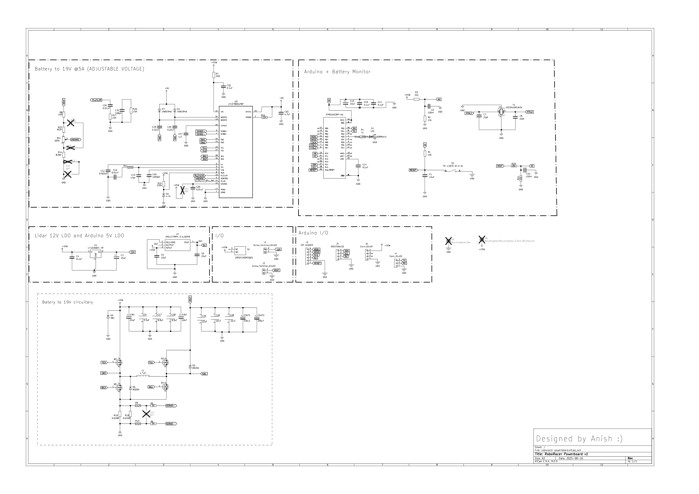
KiCad Schematic:
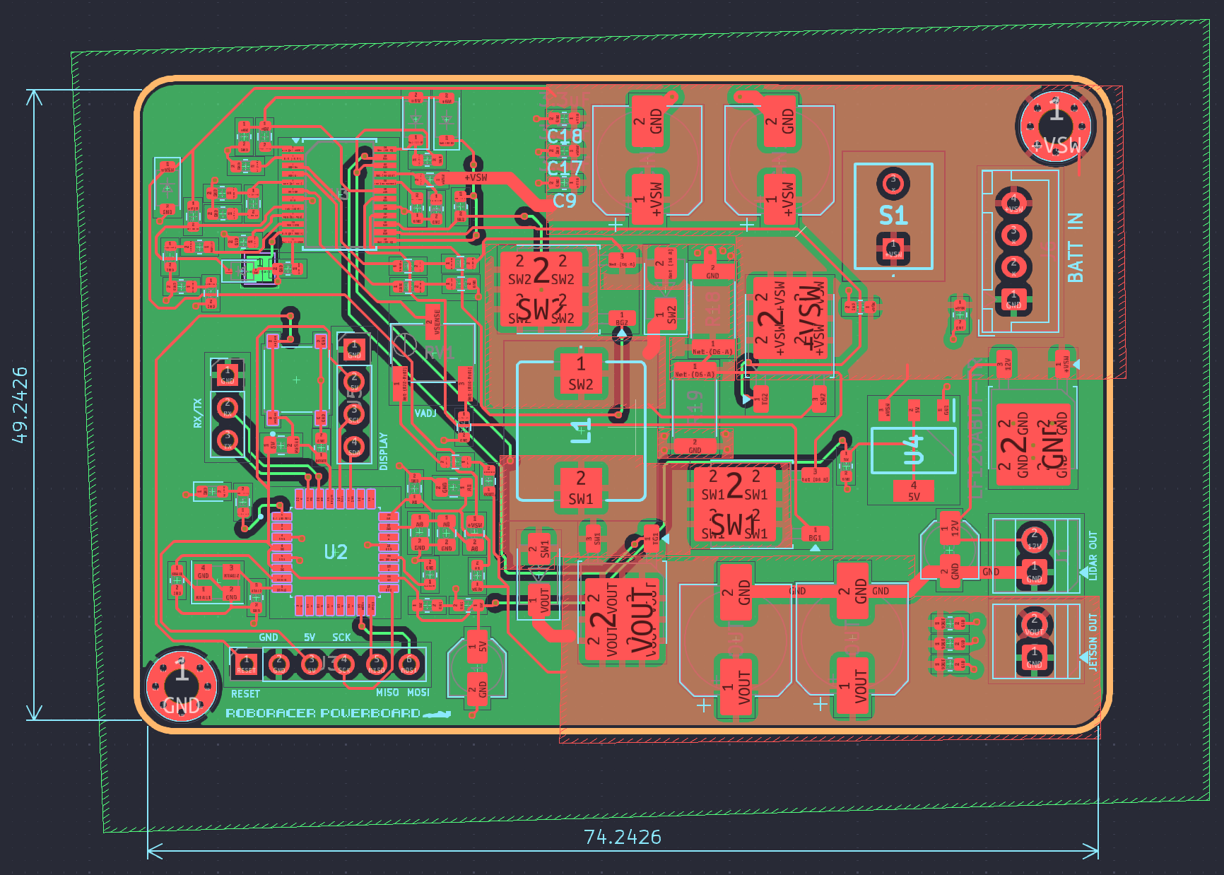
 PCB Layout:
 </a
</a
Here’s what the monitoring system does:
- Shows exact battery level on an OLED display
- Has status LEDs for quick visual feedback
- Communicates with your Jetson over serial for software integration
- Includes a reset button for the Arduino when needed
The implementation uses a voltage divider network to safely read battery voltage, and the Arduino handles all the calculations to determine percentage remaining. No more guessing, no more unexpected shutdowns during testing or competition.
The really cool part is the Jetson integration. The Arduino sends battery data over serial, so if you’re running ROS, you can display battery info right on your dashboard. Pretty useful when you’re focused on tuning algorithms and don’t want to keep checking the physical display.
Universal Power Supply Solution
This addressed another major limitation of the original design. Different Jetson boards need different power levels, but the original PCB was locked to specific voltages. Our solution? Make it adjustable.
The voltage is now configurable from 2V all the way up to 22V using a precision potentiometer. Here’s what this means for different setups:
- Jetson Nano: Dial it to 5V
- Xavier NX: Set it to 9V
- Orin Nano (what we use): Configure for 19V
- Custom requirements: Anything in the 2-22V range
And we’re talking about serious current capacity - up to 5 amps. That covers even the most power-hungry Jetson variants with room to spare.
We went with a 2-layer design, but the layer allocation is pretty thoughtful:
Bottom layer: Complete ground plane. This provides several benefits:
- Significantly reduces electrical noise (which was an issue with the original)
- Acts as a heat spreader for thermal management
- Creates clean return paths for signals
- Improves overall signal integrity
Top layer: Split planes with dedicated sections for VIN and VOUT power distribution. This approach:
- Handles high current paths without voltage drop
- Minimizes power loss through proper trace sizing
- Provides effective heat dissipation for power components
- Allows for clean routing of control signals
The trace widths are calculated for the full 5A current capacity without significant heating or voltage drop. It’s not overly complex, but it makes a real difference in performance and reliability.

Component Strategy
Most components are SMD for better reliability and smaller footprint and also makes it easdy to get assembled by JLCPCB or whatever vendor you would want to use. The project files has everything BOM,CPL and Greber and it should be one click. Some components might not be available in JLCPCB assembly so I have attached the mousser another BOM list from moussser which I have used to procure and sodler it. Soldering them should be prettty easy with some basic expierence if not I guess we can use this as a chance to learn something new ;)
Programming the Arduino
Getting Firmware Uploaded
We included ISP header pins because that’s the most reliable programming method. The process is pretty straightforward:
ISP Header Pinout:
1. MISO  4. VCC
2. SCK   5. RESET
3. MOSI  6. GND
Programming Setup:
- Use an Arduino Uno as ISP programmer (most accessible option)
- Or get a dedicated ISP programmer if you’re doing this regularly
- Arduino IDE with the necessary libraries installed
Programming Process:
- Connect your ISP programmer to the 6-pin header
- Ensure the board has 12V power applied
- In Arduino IDE: select “Arduino Uno” as board type
- Choose “Arduino as ISP” as programmer
- Use “Upload Using Programmer” (not the standard upload)
For command line programming:
avrdude -c arduino -p atmega328p -P /dev/ttyUSB0 -b 19200 -U flash:w:firmware.hexJetson Integration
Hardware Connections
Power connection is simple - connect the adjustable output to your Jetson’s power input. Just make sure to set the voltage correctly with the potentiometer first! Measure it with a multimeter before connecting anything expensive.
For serial communication:
- Arduino TX → Jetson RX pin
- Arduino GND → Jetson GND
- That’s the basic setup
The Arduino operates at 5V but we included level shifting circuitry for compatibility with 3.3V logic systems.
Software Integration
If you’re running ROS2 (which you probably are for F1TENTH), here’s how you can read the battery data:
#!/usr/bin/env python3
import rclpy
from rclpy.node import Node
import serial
import json
from std_msgs.msg import Float32

class BatteryMonitor(Node):
    def __init__(self):
        super().__init__('battery_monitor')
        self.voltage_pub = self.create_publisher(Float32, '/battery/voltage', 10)
        self.ser = serial.Serial('/dev/ttyUSB0', 9600)

        timer_period = 0.1  # seconds
        self.timer = self.create_timer(timer_period, self.timer_callback)

    def timer_callback(self):
        try:
            line = self.ser.readline().decode('utf-8').strip()
            data = json.loads(line)

            msg = Float32()
            msg.data = float(data['voltage'])
            self.voltage_pub.publish(msg)

            self.get_logger().info(f"Battery: {data['voltage']}V ({data['percentage']}%)")

        except Exception as e:
            self.get_logger().warn(f"Battery monitor error: {e}")

def main():
    rclpy.init()
    battery_monitor = BatteryMonitor()
    rclpy.spin(battery_monitor)
    battery_monitor.destroy_node()
    rclpy.shutdown()
Pretty straightforward implementation. The Arduino sends JSON-formatted data, so parsing is simple.
Assembly Process
Build Order
Start with SMD components when possible - much easier to solder small parts when you have workspace available. Then add through-hole connectors and larger components.
Install the OLED display last, and use proper standoffs so it’s not sitting directly on the PCB surface.
Testing Protocol
This is important - test systematically to avoid expensive mistakes:
- Apply 12V input (use current-limited supply if available)
- Verify all voltage rails are within specification
- Check that no components are overheating
- Test Arduino functionality and display operation
- Only then connect your Jetson
Results and Lessons Learned
What’s Working Really Well
Battery monitoring has been transformative. We haven’t had a single unexpected shutdown since implementing this system. You always know exactly where you stand power-wise.
The adjustable voltage capability makes this design truly universal. We can use the same PCB across different projects with various Jetson variants. Much more flexible than being locked to specific voltages.
Assembly and maintenance are significantly cleaner now. Everything has a logical place, connectors are positioned sensibly, and debugging is actually feasible.
Trade-offs We Made
Cost is definitely higher than the original - no point pretending otherwise. But the time savings and reliability improvements make it worthwhile for serious development work.
We could probably optimize the size further, but the current dimensions work well for the F1TENTH chassis and allow good component spacing.
I ahve attached t design files if anyopne wishes to amke some chanegs or suggest improvments feedbacks are most welcome
Available files include:
- Complete KiCad project files
- Gerber files ready for fabrication
- Pick and place files for assembly
- Arduino firmware source code
- Assembly documentation
When Things Go Wrong
OLED not displaying anything? Check I2C connections first. Verify 3.3V power supply. Try reprogramming the Arduino firmware.
Battery readings seem inaccurate? The voltage divider might need calibration in firmware. Double-check resistor values. Verify reference voltage stability.
No serial communication with Jetson? Confirm TX/RX connections are correct. Check baud rate settings match (default is 9600). Test with a simple terminal program first.
Bottom Line
We built this because the original had limitations that were making development harder than it needed to be. Now we have reliable battery monitoring, universal power compatibility, and much cleaner assembly.
Is it perfect? Not really - nothing ever is. But it’s substantially better than what we started with, and it’s made our F1TENTH development much more productive.
All the design files are available if you want to build one yourself or make improvements. That’s how these projects get better - people building on each other’s work and sharing what they learn.
This represents our current design iteration. If you build one or make modifications, we’d love to hear how it works out for you!